Introduction
Software
- General
- Individual packages
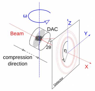
Experiment
Data processing
-
-
- Advanced topics
Post-processing and results evaluation
- cif (Crystallographic Information Format)
- inp (Input file for PolyXSim simulation)
- prm (parameter file for ImageD11)
- gve (G-Vectors)
- ini (Input file for GrainSpotter)
- edf (Format of diffraction images)
Advanced discussions