Table of Contents
MTeX
MTEX is a free Matlab toolbox for analyzing and modeling crystallographic textures by means of EBSD or pole figure data. It runs inside matlab and it is very useful to work and plot grain orientations. The homepage for MTeX is at http://mtex-toolbox.github.io/ with an extensive user manual at http://mtex-toolbox.github.io/documentation.html.
These pages do not intend to provide a full MTeX manual. We will just show tips and tricks which are useful to the community.
Note that the syntax of MTeX has been significantly changed from MTeX 5.1 to MTeX 5.4 (current version). Some of the following commands might not work depending on your version!
How to produce pole figures with MTeX
Depending on what you have as input data, the procedure might change.
Option 0: Plot individual orientations from an indexing
Once you ran an indexing, you can plot the grain orientations in MTeX.
First, you should extract a list of Euler angles for the indexed grains, which can be done using timelessExtractEulerAngles, which is part of the TIMEleSS tools. You will have a list of Bunge Euler angles (using a Bunge convention) such as
-31.88 273.49 206.05
-55.09 133.91 157.65
83.39 235.30 204.46
-47.58 78.99 149.71
-60.87 17.28 33.07
Here is an example of a script that will load these orientations and plot them in a pole figures. The example is for olivine and can be adjusted to your needs.
%%
% Define crystal and sample symmetry
cs_ol = crystalSymmetry('Pnma',[9.915267 5.886196 4.713400])
ss = specimenSymmetry()
% Plotting convention
plotx2east
% File with Euler angles
fname = fullfile('/path/to/folder/',...
    '','euler.txt');

%%
% Load file and create the corresponding list of orientations
ori = load(fname)
n = size(ori);
n = n(1);

for i = 1:n
    phi1 = ori(i,1)*degree;
    Phi = ori(i,2)*degree;
    phi2 = ori(i,3)*degree;
    ori0(i) = orientation('Euler',phi1,Phi,phi2,cs_ol,ss);
end

%%
% Plot grain orientations
h = Miller({1,0,0},{0,1,0},{0,0,1},cs_ol)
plotPDF(ori0,h,'antipodal','MarkerSize',10, 'MarkerFaceColor', 'b', 'MarkerEdgeColor', 'b')
Option 1: You have a list of Euler angles as input
For this option you need to have a text file with a list of Euler angles in the following format. There is also a TIMEleSS tool to create such a list from a Grainspotter .log file. But be aware that there are lots of different ways to arrange a set of Euler angles!
 70.469029217	237.905359456	160.103826456
 65.061195645	232.020366708	153.370063692
 -83.53256124	160.47139216	52.262899769
 81.812326561	201.132499009	220.391622469
 ...            ...             ...
Furthermore, have the correct .cif file ready. Now, go on with the following procedure:
- Load MTeX into MatLab and make sure that your workspace to the right is empty.
- Click on
Import ODF data. A new window should open. - In the new window, click on the
+symbol to the right and choose the text file with the Euler angles. A window with a short example of your data is popping up. Below, assign each column to the correct Euler angle (usually phi1, Phi, phi2). If the convention of your Euler angles is not listed, you have to convert it to another format before. - Click
Finish. The window will close and a short calculation is running. After that, the file name should be visible in the list. ClickNext». - Now, load the .cif file of your phase.
- Click
Next»until the end orFinishimmediately. - The import wizard created a script in your editor with four sections. Execute all sections starting from top by clicking
Run and advanceseveral times. - In the workspace to the right, some parameters should have appeared. They need to be there to continue. To avoid the importing procedure next time, save the current script.
- a) For plotting each and every point in a pole figure: Define a new variable:
ori = calcOrientations(odf,100), then plot by typingplotPDF(ori,Miller({1,0,0},{0,1,0},{0,0,1},CS),'antipodal','MarkerSize',4)to the command line. Depending on crystal symmetry other pole figures might be of interest. - b) For plotting a smoothened pole figure, type
plotPDF(odf,Miller({1,0,0},{0,1,0},{0,0,1},CS))to the command line. To see the intensity, clickInsert Colorbar(a button in the figure window). Depending on crystal symmetry other pole figures might be of interest. - c) For plotting orientation spot colored depending on the density of points, one need to use the fonction 'eval' as in
plotPDF(o,eval(odf,o),Miller(1,0,0,CS))where o is a set of orientations simulated from the odf (you can obtain it byo = discreteSample(odf,100)). The colorbar (if it's not showing automatically you can addmtexColorbarin the command line) is in multiple of a uniform distribution. By default it is from blue to yellow. To have it from blue to red you can use :mtexColorMap blue2red.
Another way to do it : define euler angles list as an EBSD object
First, import your list of Euler angles by : Euler = txt2mat('grainsAll_euler.txt');
then define the property of the EBSD object to be created, one by one :
[X,Y] = meshgrid(1:100,1:100)this is to create spatial information. I guess, it's needed for EBSD object.opt.x = reshape(X,1,[]);opt.y = reshape(Y,1,[]);cs = crystalSymmetry('mmm',[5.680337,11.363549,7.9293904],'mineral','Wadsleyite','color','blue');ss = specimenSymmetry('cubic');phase = 1It's also needed. Here I study only one phase so it's easy but be careful with multiple phases..phi1 = Euler(:,1)phi = Euler(:,2)phi2 = Euler(:,3)
Finaly you can create an EBSD object :
ebsd = EBSD(orientation('Euler',phi1*degree,phi*degree,phi2*degree,'ZXZ'),phase,cs,ss,'options',opt)
From here you can use tis new object as a regular EBSD object.
Option 2: You have a list of quaternions as input
Sometimes it's easier to deal with quaternions because you don't spend hours figuring out which convention was used for making them (there is only one convention for quaternions). MTeX can also read quaternions so there shouldn't be a problem. The data should be a list like this one:
0.18819093551927868 -0.011978786894112407 0.5338129942637391 -0.8243084177709855
0.9558327208154278   0.1455093219888857  -0.1091295638562596 -0.23087136099017058
0.42400840011908053 -0.2054132067385653   0.25008006803551774 0.8458618390122514
0.557578365011369   -0.6042298517163799  -0.5577004881010722 -0.11394217278021418
 ...            ...             ...           ...
Furthermore, have the correct .cif file ready. Now, go on with the following procedure:
- Load MTeX into MatLab and make sure that your workspace to the right is empty.
- Click on
Import ODF data. A new window should open. - In the new window, click on the
+symbol to the right and choose the text file with the list of quaternions. A window with a short example of your data is popping up. Below, assign each column to the correct quaternion (real, i, j, k). - Click
Finish. The window will close and a short calculation is running. After that, the file name should be visible in the list. ClickNext». - Now, load the .cif file of your phase.
- Click
Next»until the end orFinishimmediately. - The import wizard created a script in your editor with four sections. Execute all sections starting from top by clicking
Run and advanceseveral times. - In the workspace to the right, some parameters should have appeared. They need to be there to continue. To avoid the importing procedure next time, save the current script.
- a) For plotting each and every point in a pole figure: Define a new variable:
ori = calcOrientations(odf,100), then plot by typingplotPDF(ori,Miller({1,0,0},{0,1,0},{0,0,1},CS),'antipodal','MarkerSize',4)to the command line. Depending on crystal symmetry other pole figures might be of interest. - b) For plotting a smoothened pole figure, type
plotPDF(odf,Miller({1,0,0},{0,1,0},{0,0,1},CS))to the command line. To see the intensity, clickInsert Colorbar(a button in the figure window). Depending on crystal symmetry other pole figures might be of interest.
How to produce average elastic tensors from ODF with MTeX
Prerequisites
For calculating the average elastic tensors from a textured polycrystalline sample, you need several things beforehand:
- Have MTeX ready (either installed or open the “startup.m” file)
- An ODF in Matlab (can be loaded by using the import wizard, see 'How to produce pole figures with MTeX' above for more info)
- The crystal system loaded in Matlab (can be loaded by using the import wizard, see 'How to produce pole figures with MTeX' above for more info)
- The elastic tensor with all independent elastic constants
Loading the single crystal tensor
If you have these things ready, you can start by loading the elastic tensor into Matlab. Let's do it for quartz as an example.
Option 1: Manually
Type it in by hand like so: Use Shift + Return to make a new line and press Return at the very end.
>> MQuartz =....
  [[86.74  6.99  11.91 -17.91   0.00   0.00];...
  [  6.99 86.74  11.91  17.91   0.00   0.00];...
  [ 11.91 11.91 107.20   0.00   0.00   0.00];...
  [-17.91 17.91   0.00  57.94   0.00   0.00];...
  [  0.00  0.00   0.00   0.00  57.94 -17.91];...
  [  0.00  0.00   0.00   0.00 -17.91  39.88]];
Please note that the three dots at the end of each row are necessary.
Option 2: Import with the import assistant
For this, save your matrix as comma-separated values in a text file (.txt), like so:
96.6,  33.6,  21.3,   3.7,   0.,    0.
33.6,  96.6,  21.3,  -3.7,   0.,    0.
21.3,  21.3, 163.1,   0.,    0.,    0.
3.7,  -3.7,   0.,   62.7,   0.,    0.
0.,    0.,    0.,    0.,   62.7,   3.7
0.,    0.,    0.,    0.,    3.7,  31.5
Then, in Matlab go to the Home tab and click Import Data. The import assistant will open. Check if the data is in the way you want to have it and change the Output Type to Numeric Matrix. Finally, click in the Import dropdown menu on the right Generate Script. Change the name of the file in the script to whatever you like (in this example I changed it to MQuartz).
Option 3: Use the MTeX import assistant
The easiest way if you ask me. You also need the tensor as comma-separated values in a .txt file, as shown for option 2.
- In your command line, scroll all the way up until you see the three buttons for importing ODF/EBSD/pole figure data.
- Click on any of them. A new window opens.
- Switch to the tab Tensor, then click on
+on the right side of the window andopenthe file where your tensor is stored. - Click
Nextand load the CIF file of your phase. It doesn't matter if you imported it already before when you imported your Euler angles because it should be the same anyway. - Click
NextandFinish. - Run all sections of your script.
Note that the created script has already a line for assigning the matrix to the tensor. The following step is not necessary if you are loading the tensor this way.
Assigning the matrix to an elastic tensor (only for options 1 and 2)
Now, you have to tell Matlab that the variable MQuartz is not just any matrix but the stiffness tensor. We do this by typing
CQuartz = stiffnessTensor(MQuartz,CS)
to the command line. You will get a printout like this one:
CQuartz = stiffnessTensor (show methods, plot)
  unit   : GPa
  rank   : 4 (3 x 3 x 3 x 3)
  mineral: Quartz (321, X||a*, Y||b, Z||c*)

  tensor in Voigt matrix representation:
 86.74  6.99 11.91     0     0     0
  6.99 86.74 11.91     0     0     0
 11.91 11.91 107.2     0     0     0
     0     0     0 57.94     0     0
     0     0     0     0 57.94     0
     0     0     0     0     0 39.88
As you can see in this example, some of the constants have changed to zero, according to the symmetry.
Calculating the average elastic tensor
Now you can finally calculate the weighted tensor of the textured material. But be careful! A lot of memory is necessary for this kind of calculation and your computer might get stuck for a moment!
THill = calcTensor(odf,CQuartz,'Hill')
Transferring ODF data from MAUD to MTeX
How to get a texture in MAUD
MAUD is capable of calculating textures, as well as ODFs and pole figures by using the algorithm E-WIMV. This option can be found when marking a phase, clicking on the eye and choosing the tab Advanced models. In the dropdown menu Texture, you can find E-WIMV. Note that you have to unclick Normalize pole figures in Options –> Advanced options. When you do the refinement with E-WIMV for the first time, MAUD will open the save menu. This is a bug so just click Cancel. You have to click Cancel twice for each phase, for which E-WIMV should be applied. When your refinement is finished, you can export the calculated texture in a Beartex format. Beartex is another texture software. To do so, go back to options window of E-WIMV. You have two options for exporting the texture:
Export PFs (.xpc) for Beartex(exports the pole figures)Export ODF formatted (text) for Beartex(exports the ODF)
Import the MAUD texture into MTeX
Unfortunately, MTeX is not able to load an ODF, which is saved in Beartex format. Theoretically, one could modify the file in Excel by hand to make the format match, but this is extremely tedious and would probably take hours for each file.
The best way is to use the pole figure data instead. Depending on the symmetry, MAUD will create a certain amount of pole figures, which you can export by clicking Export PFs (.xpc) for Beartex. A text file is created, which can be imported into MTeX by using the Import Wizard.
Here is a step-by-step guide:
- Open the Import Wizard by typing
import_wizard - Choose the tab
Pole figuresandData - Click on the
+and choose the pole figure file (.xpc) from MAUD - Click
Nextand give your phase a name - Also, check if the cell parameters are correct and modify the point group if necessary
- Click
Nexttill the end and thenFinish - Modify the variable h in the created .m file by exchanging all x-indices with y-indices and vice-versa in every(!!!) line! This has to be done because MAUD uses a left(?)-handed coordinate system, and MTeX uses a right(?)-handed one.
- Add the following line to your script and run it:
odf = calcODF(pf)
Now you have an ODF in MTeX, which should be almost identical to the one from MAUD.
Component analysis
A component analysis provides you with the components, which “make” your textures.
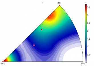
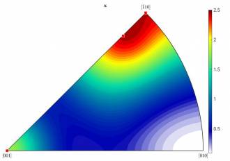
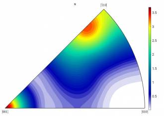
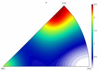
Example: Figure a) shows the inverse pole figure (IPF) of a textured material with tetragonal symmetry. Although the raw data consists of dozens of individual crystals, there are only two distinct “types” of orientations visible: at [001] and close to [-110]. A component analysis provides you the exact contribution of each of these two components.
Left: Figure a): HW = 10; right: Figure b): HW = 15
Procedure in MTeX
See https://mtex-toolbox.github.io/ODFComponents.html for more info on this chapter.
Have an odf ready in the workspace. Then, use the command
[ori, vol] = calcComponents(odf)
(works only in MTeX 5.4.0 or later). Then, call 'ori' and 'vol' individually to see their actual values. You will get something similar to this:
ori = orientation (show methods, plot)
  size: 7 x 1
  crystal symmetry : Sample (4/mmm)
  specimen symmetry: mmm

  Bunge Euler angles in degree
     phi1     Phi    phi2    Inv.
  225.667 154.883 358.816       0
    326.8 136.584 197.771       0
  219.344 72.8023 126.642       0
  180.004  100.88 314.985       0
  89.9998      90 89.9845       0
  303.529 75.4564 352.913       0
  90.0032 90.0012 224.993       0

vol =
   0.325581
   0.209302
   0.186047
   0.162791
   0.069767
   0.023256
   0.023256
You can see that MTeX calculated - very surprisingly - even seven components. To visualize these components, you can implement them in your pre-made figure, like so (see Figure c):
annotate(ori,'MarkerFaceColor','red')

 Left: Figure c): HW = 10; right: Figure d): HW = 15
These components are obviously not correct. Apparently, the texture is sharper in certain areas than it looks like in the figure. That´s why MTeX finds more components than there are actually there. To solve this issue, one has to smoothen the odf. This is done by increasing the halfwidth of the kernel (HW) when calculating the odf at the very beginning. The IPF above was created by using a HW of 10. This is how it looks like after increasing it to 15 (fig b). You can see that the IPF slightly changed. However, the data is still the same. When we calculate the components again, it looks a little bit better:
  Bunge Euler angles in degree
     phi1     Phi    phi2    Inv.
   47.944 24.0138 179.783       0
  359.975 98.2499 315.004       0
  90.0001 89.9999  90.006       0
  89.9998 90.0166 224.972       0

vol =
   0.558140
   0.348837
   0.069767
   0.023256
The number of components decreased to four. Their location in the IPF seems also much more reasonable (see Figure d). Now, you can decide either to increase the HW even more to hopefully get only the two components, which you expected, or you continue.
Interpreting the results
You now have to find out, which component belongs to which point in the IPF. For this step, it is helpful to plot the Euler sections:
figure
  plotSection(odf,'sections',18)
Note that for the cases of compression and tension experiments you have to change the specimen symmetry to 'mmm' before. For torsion and shear experiments, it should be '2'. If you don´t, the Euler space will be too large. In the Euler section plot, you can annotate again to see where your components are.
Now, try to assign your components to the location in the plot with the help of the given Euler angles. Some of them might be easy to find, other angles don´t seem to match the location in the plot at all. This is because some are represented differently. Try to subtract 90°, 180° or 360° from the angles. If this is not enough to assign the angles, try to subtract the angle from 90°.
Example: phi2 = 250°
This could mean one of the following opitions:
a) phi2 = 250° (not for crystal symmetry = tetragonal)
b) phi2 = 250° - 180° = 70°
c) phi2 = 90° - (250° - 180°) = 20°
If the values still don´t make sense you should consider modifying the HW to make sure that you can always follow what is going on.
The parameter vol gives you the volume proportion of each of the components (they are listed in the same order as the angles). If you realize that two of the components are basically the same, you can also add their proportion.
By performing this analysis on different samples (by using the same HW), you can not only see how certain textures evolve over time but also support this observation with numbers.

